The Krk Bridge links the Croatian mainland with the island of Krk in two reinforced concrete arches that meet on the small island of Sveti Marko. The larger arch spans 390 m, or about 416 m if the part of the arch below the waterline is counted; at its crown the deck stands about 67 m above the sea. The second arch spans 244 m. The total length is about 1,430 m. Ilija Stojadinović designed it with Vukan Njagulj and Bojan Možina, and Mostogradnja of Belgrade and Hidroelektra of Zagreb built it between 1976 and 1980. It opened on 19 July 1980.
Wikipedia records the main span as the longest concrete arch at the time of construction, until the Wanxian Bridge in China surpassed it in 1997. The record belongs to the finished arch. The construction story is about the years before closure, when neither half could act as an arch at all and each had to be held in place as a cantilever.
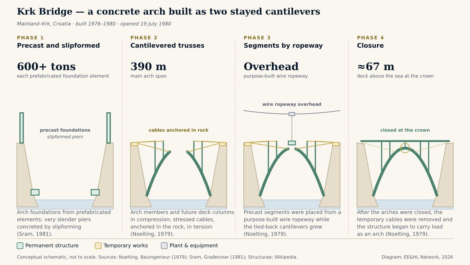
Sources: Noelting, Bauingenieur (1979); Sram, Građevinar (1981); Structurae; Wikipedia. Diagram: EE&HL Network, 2026.
Tap or click the diagram to open it full size.
At Krk, arch action depended on closure. Until then, each half worked inside a temporary tied-back cantilever system that carried the forces the arch would later carry itself.
Cantilevered arch erection with temporary ties is a recognised method for long concrete arches, and Krk is an early large-scale example of it; Wikipedia describes the bridge as designed as a cantilever bridge with temporary cable-stays. The sources reviewed describe the system but not the stage-by-stage tie forces, the closure tolerances or how geometry was controlled as the cantilevers grew. Those details are not given here.
The later jacking is worth noting. The arch was adjusted twice in its first years to correct the effects of creep and shrinkage, which shows that the geometry fixed at closure was not the final geometry. For a concrete arch, as for a concrete cantilever, construction-stage decisions continue to shape behaviour after the temporary works have gone. That is an editorial reading.
For other arches closed in the air, see the Gateway Arch and Chenab Bridge case studies. For the general question of releasing temporary supports, see What Is a De-Propping Sequence? and Temporary Works & Erection Strategy.
Related case studies: Chenab Bridge · Gateway Arch · Koror–Babeldaob Bridge · Hoover Dam · Beijing National Stadium
Core concepts: What is erection engineering? · What is heavy lift engineering?

Photo: Toffel, via Wikimedia Commons; public domain.
Sources: Bauingenieur — Noelting, D., vol. 54, no. 8, 1979, p. 314 (TRID abstract) — cantilevered trusses, cables anchored in rock, removal after closure, wire ropeway; Građevinar — Sram, S., vol. 33, no. 2, 1981, pp. 77–106 (TRID abstract) — precast elements, foundation elements over 600 t, slipformed piers; Structurae — Krk Bridges — second span, jacking of the arch after two and three years; Wikipedia — Krk Bridge — designers, contractors, dates, main span and 416 m figure, clearance, total length, record until Wanxian, temporary cable-stays. The erection method is taken from the abstracts of the 1979 and 1981 papers; the full papers were not consulted, and details of tie forces, closure and geometry control are not given here. Sources label the 67 m figure differently: Wikipedia gives a clearance below of 67.02 m, and Structurae lists 67 m as the rise. These are different geometric quantities. This page follows the 1979 abstract, which gives the deck at the crown as approximately 67 m above the sea channel, and does not present the figure as a verified arch rise. Material quantities are omitted from this account. An earlier version of this story appeared as a LinkedIn post.
Frequently Asked Questions
According to a 1979 account in Bauingenieur, each half was built outwards as a cantilevered truss: the arch members and future deck columns in compression, and stressed cables anchored in the rock in tension. Precast segments were placed from a specially constructed wire ropeway. After the arches were closed the temporary cables were removed.
The main arch spans 390 m, or about 416 m if the part of the arch below the waterline is counted. At the crown the deck is about 67 m above the sea. The second arch spans 244 m and the total length of the bridge is about 1,430 m.
Wikipedia records its main span as the longest concrete arch at the time of construction, until the Wanxian Bridge in China surpassed it in 1997.
Structurae reports that the arch was raised by jacks by 63 mm after two years and by an additional 93 mm a year later, to counter the effects of creep and shrinkage.