Attention in heavy lift goes to the lift: the moment the load leaves the ground, the hours it spends in the air, the crowd at the fence. It is the visible event, and it can receive the most attention. The moment that can carry more exposure often comes afterwards, when the load is set down and begins to move from the temporary system that carried it into the permanent structure that must carry it from then on.
This article is an editorial reading of that transition. It draws on documented projects on this site, but the pattern it describes is an observation, not a statistical finding.
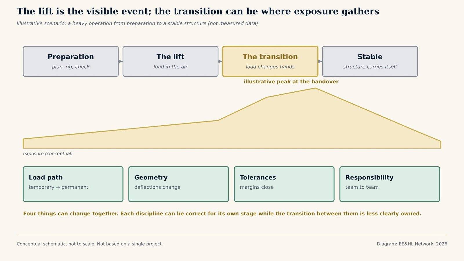
Tap or click the diagram to open it full size.
Four things can change together
What documented projects show
At the Beijing National Stadium, the primary roof structure was released from 78 temporary supports in seven major steps and 35 sub-steps, with the jack reactions and deflections measured at each stage. The measured deflection, 271 mm, came within 5.2% of the 286 mm calculated. The care went into the transition, not only into the assembly; see the Beijing National Stadium case study.
At the Millau Viaduct, the earliest release of the temporary towers was set by the stay-cable installation schedule, because the deck could only do without them once the stays carried it. The transition was a programme dependency as much as a structural one; see the Millau case study.
The Koror–Babeldaob Bridge is a different kind of transition, late in a structure’s life rather than during construction. A 1996 retrofit closed the midspan hinge and made two cantilevers into one continuous span, changing the load path in a structure that had behaved as cantilevers for nearly twenty years. WJE’s investigation identified top flange delamination as the trigger of the collapse that followed; see the Koror–Babeldaob case study.
Why the transition is easy to under-plan
The lift has a start and an end that everyone can see. The transition is a sequence of intermediate states, each of which has to be checked for a structure that is partly temporary and partly permanent. Those states are easy to treat as a single step on a programme. In practice each one is its own load case, and the people who know the temporary system best may already be preparing to demobilise.
A practical reading is that the transition deserves its own plan, its own hold points and a named owner, in the same way the lift does. That is an editorial observation, not a recommendation for any specific project.
For related patterns see What Is a De-Propping Sequence?, What Is Erection Sequence Risk? and the insight Why Removing Temporary Works Can Be Riskier Than Installing Them.
Related case studies: Beijing National Stadium · Millau Viaduct · Koror–Babeldaob Bridge · Gateway Arch · Krk Bridge
Sources: EE&HL Network — Beijing National Stadium, with its primary sources (Li et al., CIB W78 2013; China Daily); EE&HL Network — Millau Viaduct temporary towers release sequence, with its primary sources; WJE — Koror-Babeldaob Bridge project page (retrofit and collapse investigation). The exposure curve in the diagram is conceptual and does not represent measured data. The pattern described is an editorial reading of documented projects, not a statistical finding. An earlier version of the thinking in this article appeared as a LinkedIn post.
Frequently Asked Questions
It is the stage after the lift in which load moves from the temporary system that carried it, such as supports, towers or lifting equipment, into the permanent structure. It usually passes through several intermediate states rather than happening at once.
Because load path, geometry, tolerances and responsibility can all change together. Each intermediate state is its own load case for a structure that is partly temporary and partly permanent, and the step between the erection scope and the permanent works scope can be less clearly owned than either.
The primary roof structure was released from 78 temporary supports in seven major steps and 35 sub-steps, with jack reactions and deflections monitored throughout. The measured maximum deflection was 271 mm against 286 mm calculated, a difference of 5.2%.
Yes. At the Koror–Babeldaob Bridge a 1996 retrofit closed the midspan hinge and made the main span continuous. WJE’s investigation of the collapse that followed identified delamination of the top flange as the trigger, with closing the hinge raising the compressive stress in that flange.